
close
Choose Your Site
Global
Social Media
Views: 0 Author: Site Editor Publish Time: 2026-05-27 Origin: Site


Installing a new varnish roller represents a critical operational event, rather than just a routine maintenance task. Mistakes during this process often lead to uneven coating, excessive downtime, and premature equipment wear. We must treat every installation as an opportunity to optimize press performance. A truly successful installation achieves 0.01mm runout, accurate nip pressure, and optimal fluid transfer. It must also strictly follow safety protocols without causing collateral damage to the press structure.
You need a reliable, evidence-based approach to minimize production risks. This step-by-step guide provides a skeptical-friendly framework for operations managers and press operators. You will learn how to properly evaluate roller components, safely execute the installation, and mechanically verify performance before committing your machine to live production runs.
Accurate component selection—balancing upfront costs with durability—dictates long-term coating consistency.
Strict adherence to Lockout/Tagout (LOTO) and surface preparation prevents 80% of premature roller failures.
Proper journal alignment and "kiss" pressure calibration are mandatory to prevent gear damage and ensure even varnish distribution.
Post-installation dry runs and vibration analysis validate the mechanical integrity before committing to live production.
Production downtime carries a massive financial burden. Mid-installation bottlenecks amplify these costs significantly. You must audit the surrounding hardware before unpacking the new unit. This preemptive step guarantees a smooth transition. Taking time to assess the machine state prevents unexpected delays.
You should conduct a thorough baseline audit of the existing press environment. Check the current bearings, gears, and drive shafts for visible wear or excessive play. Installing a pristine cylinder into compromised housing immediately negates your investment. Worn bearings transfer vibration directly into the new unit. This causes chattering and uneven fluid distribution. We strongly recommend replacing bearings simultaneously if they show any signs of degradation.
Safety compliance remains non-negotiable during heavy equipment swaps. Always follow mandatory safety steps to protect your team. Emphasize standard Lockout/Tagout (LOTO) procedures. Isolate all electrical, pneumatic, and hydraulic power sources. Verify zero energy states before opening the machine guards. Press operators must use approved lifting equipment to handle heavy cylinders safely. Proper hoists prevent severe workplace injuries and protect delicate engraved surfaces from accidental impacts.
Environmental preparation is equally vital for a successful installation. You must clear all residual dried varnish, solvents, or debris from the mounting brackets. Contaminated bearing housings prevent flush seating. Use appropriate industrial solvents to strip away hardened residues. Inspect the side frames and journal saddles carefully. A clean operating environment guarantees accurate mechanical alignment later in the process.
Different coating jobs require specific roller specifications. You must match the cylinder technology to the specific chemistry of your fluid. UV-cured varnishes, aqueous coatings, and solvent-based fluids behave differently. They demand distinct surface energy characteristics. Selecting the correct solution category ensures optimal fluid transfer and extends the operational lifespan of the unit.
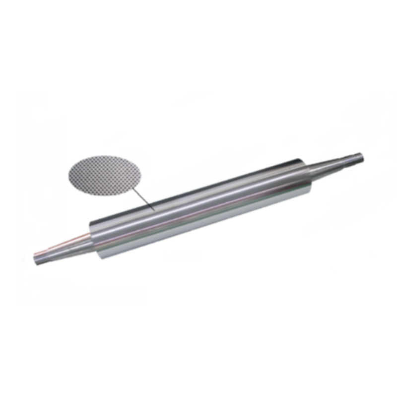
Material selection plays a defining role in long-term performance. You need to understand when to choose standard metal versus advanced ceramic options. Consider a high line metal anilox roller for standard, predictable coating volumes. Metal cylinders remain highly cost-effective for conventional applications. They deliver consistent fluid release when handling non-abrasive varnishes. Metal proves sufficient for shorter runs or facilities focusing on standardized gloss coatings.
Conversely, abrasive coatings require upgraded surface technologies. You should transition to a wear-resistant ceramic ink proofing roller when handling highly abrasive fluids like matte varnishes containing silica particles. Ceramic construction offers maximum longevity. It provides precise cell-volume retention over millions of impressions. Ceramic cylinders resist scoring and chemical degradation far better than their metal counterparts. They excel in demanding environments requiring absolute consistency.
When evaluating cost versus ROI, maintain a transparent, evidence-oriented view. Ceramic components require a higher upfront investment. However, they drastically reduce the swap frequency. This extends your production uptime considerably. Metal units offer an economical entry point. Yet, they may require stricter maintenance and more frequent replacement cycles. Balance these factors against your typical production volumes and coating chemistries.
Comparison of Roller Technologies | ||
Feature | Metal Cylinders | Ceramic Cylinders |
|---|---|---|
Primary Use Case | Standard, predictable coating volumes | Highly abrasive or specialty coatings |
Upfront Investment | Lower | Higher |
Durability | Moderate (Requires strict maintenance) | Maximum (High wear resistance) |
Cell Volume Retention | Good for standard runs | Excellent over millions of impressions |
Removing the old cylinder requires precision to avoid damaging the press frames. Follow a methodical approach to ensure safety.
Release the nip pressure completely. Ensure the cylinder floats freely without contacting the impression roller.
Disengage the drive mechanisms safely. Remove any drive belts or gear assemblies attached to the journals.
Document the removal sequence carefully. Take photographs of spacer placements and bracket orientations. This allows you to reverse-engineer the installation effortlessly.
Attach the lifting hoist using approved nylon slings. Never use metal chains. Lift the old unit vertically out of the saddles.
Handling the replacement unit correctly preserves its delicate engraved face. A single bump can destroy the microscopic cell structure.
Inspect the new cylinder before unpacking. Verify the dimensions and specifications match your press requirements.
Use clean, specialized slings or mechanical lifts for transport. Never lift the unit by touching the engraved face directly. Support it entirely by the journals.
Guide the cylinder slowly over the press frame. Lower it gently into position.
Align the journals precisely with the cleaned bearing housings. Ensure they rest fully flush against the saddle base.
Proper fastening ensures mechanical stability during high-speed operations. Sloppy securing leads to severe vibration issues.
Install the bearing caps and locking brackets. Thread the retaining bolts by hand initially to prevent cross-threading.
Apply the correct torque specifications to all locking bolts. Use a calibrated torque wrench. Over-tightening distorts the bearing housings.
Verify the gear meshing if your system uses gear-driven components. Adjust the backlash settings according to manufacturer guidelines.
Rotate the cylinder by hand. Ensure a smooth mechanical transition without binding or excessive resistance.
Calibration dictates the final quality of your printed product. The industry relies heavily on the "kiss" impression methodology. This concept advocates using the lightest possible pressure required to transfer the fluid. Over-pressuring remains a primary cause of cylinder deflection. It forces the journals to bend slightly under extreme loads. This bending creates uneven wear patterns and shortens the component lifespan drastically. Start with zero pressure. Gradually engage the mechanism until fluid transfers uniformly across the entire web.
Parallel alignment checks confirm geometric accuracy. You must verify the new unit sits perfectly parallel to the impression cylinder or substrate. Misalignment causes fluid starvation on one side of the web. We recommend using feeler gauges to measure the physical gap between the stationary cylinders. Alternatively, use specialized impression tape. Apply the tape across the web width, engage the nip lightly, and measure the resulting stripe width. A uniform stripe indicates perfect parallel alignment.
Measuring Total Indicator Reading (TIR) validates the mechanical concentricity. You must measure runout using a high-precision dial indicator.
Mount the dial indicator on a stable, magnetic base attached to the press frame.
Place the stylus directly against the unengraved dead band of the cylinder.
Rotate the cylinder slowly by hand for one complete revolution.
Monitor the gauge deflection. A trustworthy installation must fall within strict manufacturer tolerances. This typically means staying within fractions of a thousandth of an inch.
High TIR values point to improperly seated bearings or bent journals. Resolve these issues immediately before applying power.
Verification separates a completed installation from a successful one. We must validate the mechanical integrity before beginning live production. Start by conducting thorough vibration and acoustic checks. Perform a low-speed "dry run" without fluid. Listen closely to the machine. Unusual noises indicate underlying problems. Grinding sounds suggest bearing failure or severe contamination. Rhythmic clicking often points to damaged gear teeth or tight gear mesh. Address any anomalous vibrations immediately. They will amplify significantly at standard production speeds.
Next, initiate fluid transfer testing. Engage the fluid delivery system and run a proofing test on waste substrate. You need to check for specific coating defects. Look closely for pinholing, where the varnish fails to wet out properly. Check for ribbing, which looks like raised stripes running parallel to the web direction. Ensure an even laydown across the entire width. Consistent gloss levels confirm accurate fluid metering and proper pressure settings.
Even meticulous installations encounter occasional snags. You need a structured troubleshooting approach to resolve issues rapidly. Use the following diagnostic chart to identify and correct common implementation risks.
Troubleshooting Guide for New Installations | ||
Observed Issue | Root Cause Analysis | Corrective Action |
|---|---|---|
Varnish starvation on edges | Bowing of the cylinder or uneven nip pressure. | Recalibrate parallel alignment. Reduce overall nip pressure to prevent deflection. |
Chatter marks on substrate | Gear mesh too tight or early bearing failure. | Adjust gear backlash. Verify bearing seating and inspect for damage. |
Uneven gloss (side to side) | Tapered gap setting. | Use impression tape to reset parallel positioning precisely. |
Excessive foaming in pan | Air entrapment from high speeds or loose fittings. | Check pump seals. Adjust rotation speed during the break-in period. |
After verifying performance, you should shortlist your next steps. Advise decision-makers to standardize the procurement process moving forward. Create a strict internal checklist for future replacements. This ensures your preferred vendors supply consistent specifications every time. Standardization removes guesswork from future installations. It builds a reliable baseline for your maintenance team.
A methodical installation protocol safeguards your investment in high-quality coating equipment. Skipping foundational steps like baseline audits or LOTO compromises both safety and production quality. Relying on precision measurement tools over visual guesswork ensures long-term consistency. By utilizing techniques like the "kiss" impression and dial indicator runout checks, you prevent premature wear.
Your actionable next step is establishing a strict preventative maintenance schedule immediately. Start this routine from day one of the new installation. Implement regular cleaning cycles using approved solvents. Schedule monthly cell inspections using microscopic tools. Proactive maintenance preserves the delicate engineered surface, ensuring optimal performance for years to come.
A: A standard installation takes between 2 to 4 hours. This timeline depends heavily on machine size, accessibility, and the condition of existing bearings. Comprehensive cleaning and calibration account for most of this duration.
A: No, you must verify chemical compatibility. Harsh caustics or strong acids might degrade bare metal cylinders rapidly. Ceramic surfaces offer much broader chemical resistance, allowing for more aggressive cleaning agents.
A: You should recalibrate immediately after the physical installation. Perform a second check after the first production shift, as new components often settle. Afterward, integrate pressure checks into your routine weekly maintenance schedule.
A: Immediate visual defects in the coating provide the clearest indicators. Look for severe banding, continuous pinholes, or uneven gloss levels across the web. Unusual mechanical noise or noticeable vibration also signals improper seating or alignment.


